Description
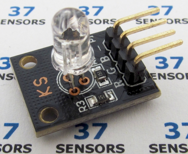
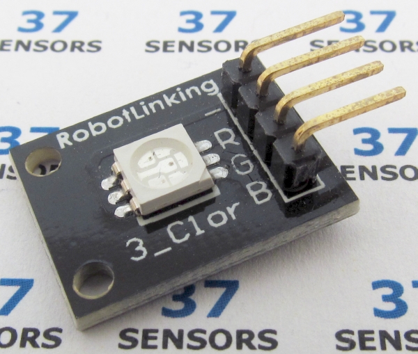
LED containing red, green, and blue emitters, each controlled independently.
Also called: full color LED, three color LED, tri-chromatic LED, KY021, KY016.
Found in kits: 37 sensors, 45 sensors (through-hole LED).
Found in kits: 20 sensors, 37 sensors, 45 sensors (SMT LED).
Specification/Notes:
LED: Either TH or SMT 5050
Forward voltage drop red: 2.1V
Forward voltage drop green: 3.2V
Forward voltage drop blue: 3.2
Red: 625nm
Green: 530nm
Blue: 465nm
Size: 20mm X 15mm
Some modules have current limiting resistors, some do not. The typical resistance value is 120 – 270 Ohms.
Pins are frequently labeled incorrectly. RGB, BGR, GRB, etc.
There are a number of different sources for these modules. Not every module that looks similar to the ones here behaves exactly the same. Check the specific module that you have for differences in function, voltage levels, pinout, and inactive/active states. Some modules have been found to have incorrectly labeled pins and even poorly soldered components.
Module Pin-out:
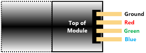
Typical/common pinout. Always check the pinout for the module that you have.
Test setup with CGMICROKIT1
To demonstrate how this works, a test setup that uses the CircuitGizmos CGMICROKIT1 (credit to Robert Severson) will be used. The CGMICROKIT1 has a microcontroller that connects to a PC via a USB/serial interface and runs an easy-to-understand yet powerful interpreted BASIC language (credit to Geoff Graham).

But this isn’t your 1980’s BASIC. This is a fantastic implementation of BASIC. No line numbers, made for easy understanding, and advanced microcontroller features.
This setup combines a CGMICROKIT1 with a single solderless breadboard, a USB/serial interface to the PC, and a suitable power supply for a convenient test bed for proving out small circuitry and experimenting with these 37+ sensors.
On the PC a program called MMEDIT (credit to Jim Hiley) helps to make development easier by providing a platform for editing and downloading the code used for these examples. This development environment is simple, powerful, and flexible. Alternate interfaces on the PC are any serial terminal application, including GFXterm. GFXterm (credit to Robert Rozee)
For more information about this test setup please see the information about the setup here: http://circuitgizmos.com/documentation/hardware-datasheets/cgmicrokit1-technical-information/cgmicrokit1-test-setup/
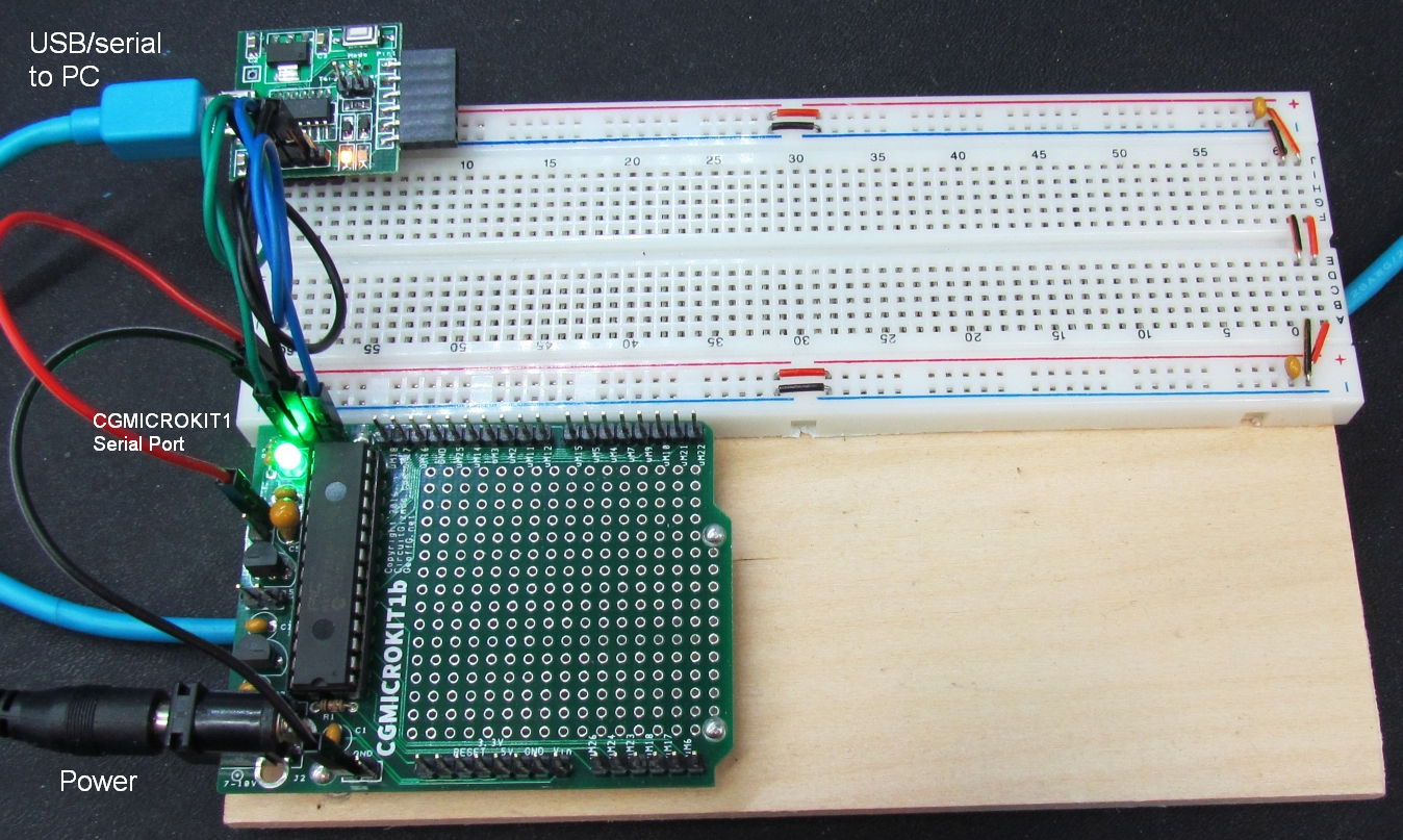
The hardware for the test setup is mounted on a small wooden base. The tested devices are added to this test setup with jumper wires.
If you have any additional information on this sensor/device or have comments, please leave a reply below.
Leave a Reply